US Patent 7,791,353 B2
Introduction
Simple Circuit Concepts
Transmission lines
Faraday's law
Near and far fields
Spurious coupling mechanisms
- Direct conduction
- Capacitive coupling -problem
- Capacitive coupling -fixing
- Inductive coupling-problem
- Inductive coupling -fixing by twisted
- Inductive coupling -fixing by coax
- Electromagnetic pickup
- Examples
- Safety & star grounding
- Gnd loop resistance, inductance
- Low frequency behavior
- High frequency behavior
- Troubleshooting
- Methods for removing
Ground loop resistance, inductance
The resistance and inductance of ground loops can best be understood using the example of a specific coaxial cable, say a length of RG/58 (the behavior of twisted pair cables is essentially the same but the mathematical analysis is considerably more difficult and obscures understanding). Let b be the outer or shield conductor radius and for RG/58 coax, b=1.5 mm. Let k be the shield resistance per length and for RG/58 coax k= 14 milliohms/meter.
Now assume that the two ends of the shield are connected together to form a torus having major radius r and minor radius b as sketched in the figure below. This is the topology of a ground loop. If r = 5 meters, then the shield resistance is R=2pkr= 0.4 Ohms.
Find ground loops fast!
-eliminate electical interference, fix star grounding
-eliminate electical interference, fix star grounding
US Patent 7,791,353 B2
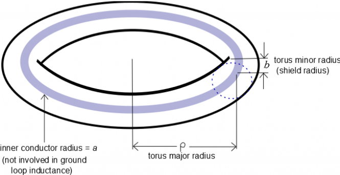
Direct calculation shows that the inductance of such a toroid (current loop) is L= m0r[ln(8 r/b) - 2]. For the RG/58 loop example under consideration and using m0 =4p x 10-7 it is seen that L = 50 microhenries; this inductance should not be confused with the inductance between the inner and outer conductors of the coax which in this case is 6 microhenries since RG/58 has 200 nH per meter inductance between inner and outer conductor and the cable length is 30 meters. A current flowing in this torus consisting of the cable shield will decay as exp(-t/t) where the characteristic decay time t=L/R. Thus, the current and its associated magnetic flux do not decay if t is much smaller than t a situation which corresponds to frequencies f much larger than R/2pL. The shield of this RG/58 example therefore behaves as a flux conserver for frequencies much larger than 1 kHz and for such frequencies the actual value of the shield resistance is unimportant. Flux conservation can be understood by using Faraday's law V= -dF/dt together with the condition V=0 to obtain F=constant; the condition V=0 corresponds to short circuiting the gap in the loop in the Faraday's law sketch.
An actual ground loop will in general not be in the shape of a perfect circle and so its inductance cannot be calculated so directly. However, the inductance will have a qualitatively similar dependence, i.e., be proportional to the mean major radius of the loop and to the logarithm of the ratio of the major to minor radii. Because the logarithm function is only sensitive to the order of magnitude of its argument, one can assume that r is always of the order of meters and the cable shield radius is always of the order of millimeters so ln(8 r/b) is ln(8000)=8.9. Reducing b by a factor of two for example would give ln(16000)=9.6. Thus, the inductance of any ground loop involving cables which are meters in length and with shields which are millimeters in radius will be of the order of tens of microhenries. Since the resistance of a cable which is meters in length is of the order of tens of milliohms, the crossover frequency
R/2pL is of the order of hundreds of hertz to several kilohertz. Thus powerline frequencies (50 or 60 Hz) will be in range where the cable resistance dominates, whereas any linked AC flux that is above a few kilohertz will be in the range where the cable inductance dominates and its resistance is unimportant. Thus powerline frequencies (50 or 60 Hz) will be in range where the cable resistance dominates, whereas linked AC flux that is above a few kilohertz will be in the range where the cable inductance dominates and its resistance is unimportant. If resistance dominates then the physical layout is unimportant while the conductor resistance is important, whereas if inductance dominates, the conductor resistance is unimportant but the physical layout is important (e.g., whether the cable is coiled).