US Patent 7,791,353 B2
Introduction
Simple Circuit Concepts
Transmission lines
Faraday's law
Near and far fields
Spurious coupling mechanisms
- Direct conduction
- Capacitive coupling -problem
- Capacitive coupling -fixing
- Inductive coupling-problem
- Inductive coupling -fixing by twisted
- Inductive coupling -fixing by coax
- Electromagnetic pickup
- Examples
- Safety & star grounding
- Gnd loop resistance, inductance
- Low frequency behavior
- High frequency behavior
- Troubleshooting
- Methods for removing
Safety and Star grounding
To prevent the possibility of electric shock, electrical safety codes require grounding of all exterior conducting surfaces of electrical and electronic devices. Grounding arrangements required for conformance with electrical safety codes can easily cause ground loops to be introduced. Since, it is imperative to follow safety codes to avoid personnel injury and possible electrocution, the challenge is to satisfy safety requirements and yet avoid ground loops. Grounding means connecting to a conductor that is in turn connected to earth (e.g., a water pipe that goes through the earth or a dedicated grounding rod buried in the earth). Grounding the chassis of a device provides safety because any internal fault that causes application of life-threatening mains voltage to the chassis will immediately cause a fuse to blow or a circuit breaker to trip and so remove the dangerous mains voltage from the chassis. Typically the power cord of a device has a third wire connecting the chassis to building ground. This ground wire is represented as R1 for device A and R3 for device B in Fig.10. Alternatively, device B could be a sensor (e.g., a thermocouple) and R3 could represent an accidental short to ground of the shield of the cable to the sensor.
To prevent the possibility of electric shock, electrical safety codes require grounding of all exterior conducting surfaces of electrical and electronic devices. Grounding arrangements required for conformance with electrical safety codes can easily cause ground loops to be introduced. Since, it is imperative to follow safety codes to avoid personnel injury and possible electrocution, the challenge is to satisfy safety requirements and yet avoid ground loops. Grounding means connecting to a conductor that is in turn connected to earth (e.g., a water pipe that goes through the earth or a dedicated grounding rod buried in the earth). Grounding the chassis of a device provides safety because any internal fault that causes application of life-threatening mains voltage to the chassis will immediately cause a fuse to blow or a circuit breaker to trip and so remove the dangerous mains voltage from the chassis. Typically the power cord of a device has a third wire connecting the chassis to building ground. This ground wire is represented as R1 for device A and R3 for device B in Fig.10. Alternatively, device B could be a sensor (e.g., a thermocouple) and R3 could represent an accidental short to ground of the shield of the cable to the sensor.
Find ground loops fast!
-eliminate electical interference, fix star grounding
-eliminate electical interference, fix star grounding
US Patent 7,791,353 B2
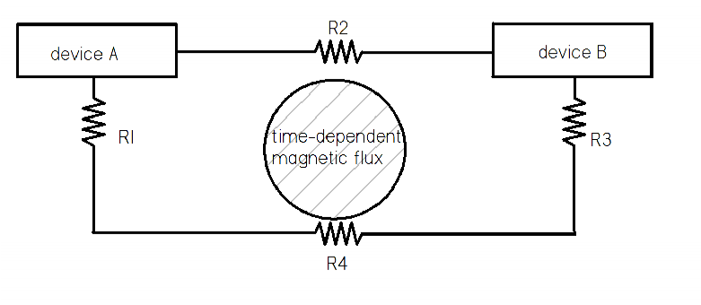
Fig. 10 Ground wires forming ground loop.
The time-dependent magnetic flux linking the loop in Fig. 10 could come from magnetic fields produced by fluorescent light fixtures, electric motors, power transformers, switching power supplies, AC currents in adjacent circuits, lightning bolts, or electromagnetic waves from a distant radio transmitter. The induced voltage will have waveforms related to the time-dependence of the magnetic source. Because ground loops depend on linked magnetic flux, they depend on the physical arrangement of the wiring and are inherently non-localized. If the magnetic source is transient, the interfering signal will also be transient and so will be an elusive 'glitch'. Ground loops are often a serious problem when small signals are being measured from multiple sensors (e.g., multiple thermocouples, optical detectors, microphones, accelerometers) because spurious grounding of just one sensor will affect the integrity of the entire system.
Strictly speaking, one cannot say where a ground loop is located because a loop does not have a specific location. This is true if the ground loop is a result of poor design or cable arrangement. One can simply determine which system of cables comprises the ground loop and then the arrangement must be changed to eliminate the loop.
On the other hand, ground loops often occur because of an accidental short to ground of a conductor that is already grounded elsewhere. For example the metal shield of a coaxial cable connector might accidentally touch a grounded metal surface and so establish a loop; the resistance of the touching point would correspond to R3 in Fig.10. Such a loop is neither intended nor required, but nevertheless links spurious time-dependent magnetic fields and so produces interfering signals. The location of the accidental short to ground in this situation could be considered as the location of the ground loop.
The definitive way to avoid ground loops is to use a star grounding as shown in Fig. 11; the resistors represent the shields (ground wires) of cables and the central dot represents the common ground. In this system there is a single ground point so no loop exists. However, star grounding can be violated when instruments are connected together.
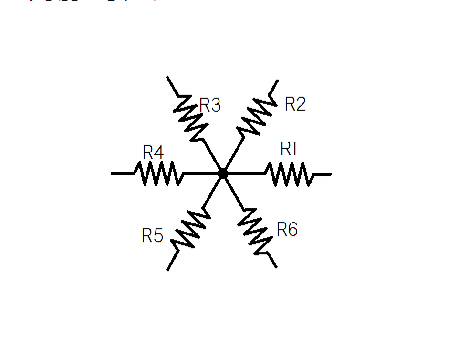
Fig. 11 Star ground system. Resistors represent ground cable of each device. Center dot is building ground. There are no loops.